
Understanding Efficiency in DC-DC Boost Converters
A DC-DC step up converter, also called a boost converter, changes lower input voltages into higher output voltages while using less power. It does this by storing electricity in inductive coils and switching at high frequencies. The main problem in power electronics is how to connect low-voltage sources (like 5V USB ports or 12V car buses) to high-voltage loads (like network equipment, video systems, and industrial sensors). This technology solves that problem. In areas like consumer technology, renewable energy, industrial automation, and smart buildings, the efficiency of these converters has a direct effect on running costs, system stability, and thermal management.
Introduction
For modern business-to-business uses, power conversion solutions must strike a balance between performance and cost-effectiveness. Your total cost of ownership depends on how well your converter works, whether it's powering remote surveillance cameras, keeping voltage stable for industrial control systems, or connecting solar panel outputs to battery management systems. Poor efficiency means wasting energy, making too much heat, and shortening the life of parts, all of which hurt profits in large projects.
This guide is for procurement experts, design engineers, and decision-makers who want to know how to choose, optimise, and keep high-efficiency boost converters in a useful way. We'll look at how choosing the right parts, designing for heat, and working with suppliers can affect performance in the real world. If you know about these technical and business aspects, you can make smart decisions that will improve project results while keeping costs low.
Fundamentals of DC-DC Boost Converter Efficiency
Core Operating Principles
During switching stages, DC-DC step up converters use the feature of an inductor to store energy. An electric field is created when the internal MOSFET shuts off and current runs through the inductor. When the gate opens, the falling field sends high-voltage energy stored in it to the output capacitor and load. This switching can happen anywhere from thousands to millions of times per second, depending on the switching frequency of the design.
To understand efficiency, you need to look at where energy is lost during this process. There are two main types of loss: switching losses that happen when a transistor changes states and conduction losses that happen when resistive elements in the current path wear away. Good inductors with low DC resistance cut down on transmission losses, and new MOSFETs with lower on-resistance (R_DS(on)) make the whole system more efficient.
Factors Influencing Efficiency Performance
Choosing the right components is key to getting the most out of your system. In regular designs, Schottky diodes lower the forward voltage drop. But in premium modules, replacing the diode with a second MOSFET and using synchronous rectification completely gets rid of this loss. It doesn't matter what the operating conditions are; efficiency curves usually peak at 50–70% load and drop at light loads when the control circuitry's idle current becomes relatively important.
Temperature has a direct effect on how well semiconductors work. When the junction temperature of a MOSFET goes up, the on-resistance goes up. This creates a feedback loop where heat lowers efficiency, which makes more heat. Using heatsinks, airflow, or thermal vias in PCB plans to handle heat properly keeps parts within the best temperature ranges, keeping them working efficiently in all types of weather.
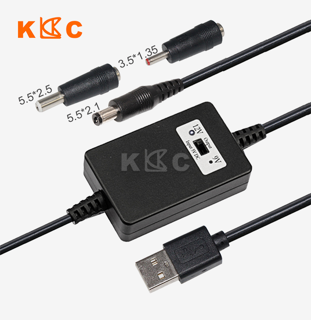
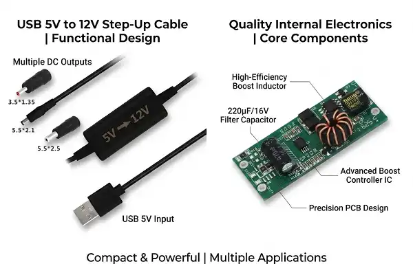
In well-designed systems, modern DC-DC step up converters can reach 90 to 96% efficiency. Kuncan Electronics makes a USB to 12V boost converter that is more than 90% efficient. It does this by using smart IC technology that balances switching frequency, component quality, and thermal performance. Before it is shipped, every unit is put through a full set of electrical tests to make sure it meets the efficiency requirements.
Industry Standards and Benchmarks
Different application areas have different efficiency standards. To balance cost and performance, consumer electronics usually aim for 85 to 90% efficiency. Industrial-grade solutions, on the other hand, need 92 to 95% efficiency to justify higher component costs through operational savings. In medical and automotive settings, it's important that the efficiency stays stable at all temperatures. Our industrial products meet AEC-Q100 automotive qualification standards and keep working as expected from -40°C to +85°C.
To measure efficiency, you need precise tools that can record both input and output power at the same time across a range of loads, and for a DC-DC step up converter, this testing is critical because efficiency varies significantly with load current, input voltage, and temperature, and selecting a converter without reviewing its efficiency curve can lead to unexpected thermal and performance issues in the final system. Standard test procedures in the industry include measuring points at 25%, 50%, 75%, and 100% of the maximum load. These points are used to make efficiency models that show how the device works in real life. These curves help buying teams match the skills of converters with the needs of applications.
Analyzing and Optimizing Efficiency: A Performance Optimization Approach
Diagnosing Efficiency Bottlenecks
Systematic measurement is the first step in finding performance problems. Thermal imaging shows hotspots that mean certain parts are losing too much power. For example, overheated inductors could mean that the core is saturated or the wire gauge is too small, and hot MOSFETs could mean that the switching losses are too high or there isn't enough gate drive. When you look at switching waveforms on an oscilloscope, you can see things like ringing, voltage overshoot, or slow transition times that waste energy.
Load testing across the working range creates efficiency charts that show exactly where performance starts to drop. When control ICs go into pulse-skipping mode to keep regulation, they often lose efficiency in light loads. They do this by giving up output stability for efficiency. Heavy-load efficiency goes down when parts get close to their temperature or current limits, which makes resistance losses worse.
Advanced Optimization Techniques
By making sure MOSFETs switch on at zero voltage or zero current moments, soft-switching techniques lower switching losses. Zero-voltage switching (ZVS) methods use resonant circuits to get rid of parasitic capacitance before the transistor turns on. This stops the energy that is lost when these capacitances are charged and discharged millions of times per second. Implementation gets harder, but in high-volume uses, the gains in speed make the engineering work worth it for a DC-DC step up converter.
MOSFETs that are constantly controlled are used instead of lossy diodes in synchronous rectification. Traditional Schottky diodes drop 0.3 to 0.5V no matter how much current they have. A MOSFET, on the other hand, has an on-resistance that makes its voltage drop proportional to the current. This leads to a big increase in efficiency at higher currents—converting a 2A load with 0.4V diode drop wastes 0.8W, but a MOSFET with 50mΩ on-resistance only wastes 0.2W.
Practical Component Upgrades
When you choose MOSFETs with low R_DS(on), you directly cut down on conduction losses. Resistive power loss is cut by 70% when devices from 100mΩ to 30mΩ are switched to the same current level. This improvement has to be weighed against the need for a higher gate charge. Lower resistance usually goes with higher gate capacitance, which makes switching losses higher. To get the best results, you need to match the MOSFET's properties to certain working speeds and current levels.
Low core losses in high-frequency inductors let them be smaller without losing any effectiveness. Compared to older materials, newer ferrite cores made for megahertz operation have lower hysteresis and eddy current losses. The wire diameter needs to be able to handle RMS current without too much resistive loss, and the saturation current value needs to be higher than the peak inductor current by a sufficient amount.
Our power solutions for surveillance cameras show how these ideas work in real life. We get stable 12V output from 5V USB sources with little heat generation by using low-resistance MOSFETs, optimised inductance designs, and smart thermal management. The SAE quick-disconnect link keeps the contact resistance low, which keeps the power flow efficient from the source to the load.
Comparing DC-DC Boost Converters with Alternative Solutions
Boost Converters vs. Buck Converters
The need for voltage exchange determines the choice of structure. DC-DC step up converters work great when the output voltage needs to be higher than the input voltage. For example, they can power 12V devices from 5V sources or raise the voltage of a battery as it drains. Buck converters do the opposite of what they're supposed to do; they step down voltage well but can't raise voltage. Applications that need both functions use buck-boost topologies, which are more expensive and complicated.
Different topologies have different efficiency traits. Buck converters usually get 95–98% efficiency because the current lines are easier and the voltage stresses on the parts are smaller. DC-DC step up converters are 90–96% efficient, with a small difference due to higher output voltage losses that are multiplied. This difference in efficiency affects how much it costs to run deployments that use a lot of power.
Linear Regulators and Charge Pumps
Linear regulators are easy to use and produce little noise, but they give off heat when they have too much voltage, which means they aren't good for applications that need to step up the voltage or deal with large voltage differences. It takes 7W of heat for a linear regulator to change 12V to 5V at 1A, which is 58% of the energy it uses. No matter what the voltage ratio is, DC-DC step up converters stay efficient by turning waste heat into useful output power.
Charge pumps use switching capacitor networks instead of inductors to double or multiply power. Even though it is small and doesn't produce much electromagnetic interference (EMI), it loses a lot of efficiency when it's loaded, and the voltage multiplication factors stay the same. When the power level goes above a few hundred milliwatts, DC-DC step up converters offer better load control and efficiency with an output voltage that can be changed.
Decision Metrics for Procurement Teams
To choose the right power conversion technology, you have to look at a lot of factors at once. Voltage range compatibility makes sure that the converter works with expected changes in the input voltage. For example, battery-powered systems lose voltage when the batteries are discharged, so they need converters that can keep control across a wide input range. Our USB-powered DC-DC step up converters keep the 12V output stable even when the USB port voltage changes from 4.5V to 5.5V.
Ratings of efficiency must take into account not only peak values but also real working conditions. In situations where power needs change, a converter that is 95% efficient at 50% load but only 75% efficient at 10% load is not useful. Look at the efficiency curves for the load range that your program sees most often. Noise sensitivity affects the choice of topology. For example, switching converters create electromagnetic interference that needs to be filtered and carefully planned out, while linear regulators provide cleaner output but at the cost of lower efficiency.
Size limitations are becoming a bigger factor in selection decisions. Higher switching frequencies let inductors and capacitors be smaller, which saves space on the board. Our small DC-DC step up converter designs include filtering and protection circuitry in very small packages that can be used in places with limited space, like remote network equipment enclosures and surveillance camera housings.
Procurement Strategies for High-Efficiency Boost Converters
Evaluating the Supplier Landscape
There are a lot of different kinds of power conversion options on the market, from standard units to custom-built systems. Well-known chipmakers like Texas Instruments and Analog Devices offer well-documented IC controllers that need external parts. These controllers give you flexibility but make the design more difficult. Module makers offer bundled solutions with steady performance, giving up customisation for faster deployment.
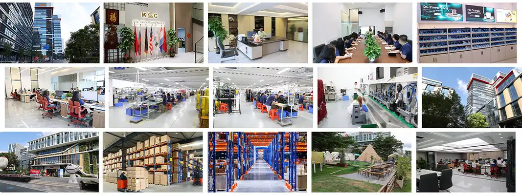
Picking a supplier is more than just looking at technical specs. Quick technical support speeds up integration and troubleshooting, lowering the risks of time-to-market. Full details, like efficiency graphs, temperature derating data, and application notes, help designers make smart choices. Kuncan Electronics has been making things for 17 years, and our experience helps buying teams make decisions about which specifications to use.
Off-the-Shelf vs. Custom Solutions
Standard catalogue modules are used in situations where the voltage and power amounts are similar. Because they are made in large quantities, these products have low prices and short lead times. Spreading the costs of testing and approval across larger batches of products lowers the cost per unit, which makes standardised solutions appealing for medium- to large-scale deployments.
Customisation is useful when the needs of a program are different from what is normally available. Custom development is worth it even though it costs more and takes longer because it includes special input/output connections, wider temperature ranges, or built-in safety features. We offer OEM branding and custom RJ45 pinout configurations to meet specific integration needs. This helps brands stand out and makes installation easier.
When planning a procurement strategy, lead time issues have a big impact, and for a DC-DC step up converter, these timelines are particularly important because they affect the overall project schedule, from prototype validation to final production ramp-up. Samples can be sent within 3–7 business days, which allows for quick prototyping and design confirmation. Mass production lead times of 15 to 25 days help keep projects on schedule when they are coordinated with production schedules. With 24-hour reaction times for rush orders, urgent needs are given priority, and plan disruptions are kept to a minimum.
Certification and Quality Verification
To get into global markets, you need to get the right safety certifications. ETL approval lets products be sold in the US and Canada, while VDE and CE marks let products be sold in Europe. SAA certification meets the needs of both Australia and New Zealand. RoHS and REACH compliance make sure that materials follow environmental rules, which keeps them from getting in the way of market access. These certifications are on our products, which makes it easier for you to keep up with regulatory requirements.
Quality security goes beyond just getting certified. Consistent manufacturing methods make sure that all output runs meet the requirements. The factories that are ISO-certified check the quality of arriving materials, check the quality of work in progress, and test the products thoroughly at the end. This methodical approach makes sure that thousands of units work reliably, which lowers the number of failures in the field and warranty claims that cut into project profits.
Troubleshooting and Maintaining High Efficiency in Boost Converter Systems
Common Efficiency Degradation Issues
Thermal stress speeds up the ageing process of parts. When temperatures rise, electrolytic capacitors, which are often used for input and output filtering, have shorter lives—every 10°C rise in temperature roughly halves the expected lifetime. By keeping an eye on working temperatures during the initial launch, you can find problems with poor cooling before they happen. Putting units in places with good airflow and away from heat sources will make them last longer.
Ageing parts slowly lose their ability to do their job. Over time, the equivalent series resistance (ESR) of a capacitor goes up, which makes the output ripple and conduction losses worse. When the temperature of an inductor core material changes, the magnetic properties can change. Taking regular readings of efficiency during planned maintenance finds signs of wear and tear before they affect how the system works, which lets you change parts before they break.
Systematic Troubleshooting Methodology
Problems with efficiency show up as measured signs. If the output voltage drops when there is a load, it means that either the resistive losses are too high or the inductor current capacity is not high enough. When temperatures are high, losses are localised to certain parts. Measurements of input current that are higher than what power conservation models say should happen show that efficiency is decreasing.
An oscilloscope study shows that the switching isn't working right. If switching nodes are ringing too much, it means there are problems with the layout or not enough snubbing. When MOSFET changes are slow, it means that the gate drive isn't strong enough. These weird waveforms directly lead to less efficiency because they cause more switching losses and electromagnetic interference.
Our built-in overcurrent and short-circuit protection makes it easier to figure out what's wrong. The smart IC keeps an eye on the flow of power and turns off the output when safety levels are reached. This keeps parts from getting damaged during fault conditions and makes it clear that the stop was caused by outside problems, not a failure of the converter.
Preventive Maintenance Strategies
Regular inspections make things last longer. A visual inspection shows any physical damage, corrosion in the connectors, or contamination that is affecting performance. Thermal imaging during operation shows areas that are starting to form before they become really inefficient. Electrical testing records initial measures of efficiency, revealing patterns that show when preventative repair is more cost-effective than continuing to operate.
Protecting the environment keeps things working well over time. Our outdoor solutions, which are rated IP67/IP68, can handle dust, water, and UV light, which quickly break down converters that aren't protected. The SAE waterproof connection keeps its low contact resistance even when it's exposed to the elements. This makes sure that power is delivered efficiently for the entire service life. This safety is very important for solar applications and surveillance systems that work in places that can't be managed.
Conclusion
Efficiency in DC-DC step up converters is more than just a set of scientific numbers; it has a direct effect on business costs, system stability, and where a company stands in the market across all industries. When procurement teams and engineers know how component choice, thermal management, and real-world performance are connected, they can make smart choices that balance the initial investment with the total cost of ownership. The tips in this article, which range from improving parts to evaluating suppliers, can help you choose and maintain high-efficiency power conversion solutions. As the need for power rises in smart infrastructure, industrial automation, and green energy, design and procurement methods that focus on efficiency will become more and more important for separating successful projects from costly failures.
FAQ
What voltage ranges do boost converters typically support?
Depending on their design, DC-DC step up converters can work with a wide range of inputs. In most cases, these configurations can take 3–20V inputs and send out 5–48V, but some designs can make these ranges bigger. Efficiency is affected by the voltage ratio between the input and output. In general, higher step-up ratios make efficiency lower because they put more stress on the components through higher currents. Our USB to 12V converters can handle a nominal 5V input and can handle voltage changes between 4.5V and 5.5V. They then output a stable 12V that can be used for network tools and security cameras.
Can efficiency be improved without complete system redesign?
Targeted component upgrades often lead to improvements that matter. Using lower on-resistance MOSFETs instead of standard MOSFETs lowers conduction losses with only minor changes to the circuit. When you switch to low-ESR capacitors, ripple current losses go down. By using better copper pours or thermal vias to manage PCB heat, operating temperatures can be lowered. This increases efficiency indirectly by lowering losses that depend on temperature. Most of the time, these changes make things 2 to 5 percent more efficient without making any major changes to the structure.
Are low-noise boost converters available for sensitive equipment?
Even though switching converters naturally produce electromagnetic interference, there are a number of ways to reduce noise. Diode reverse-recovery noise is taken care of by synchronous rectification. Spread-spectrum switching frequency modulation spreads EMI energy over larger bandwidths, which lowers the highest amounts of interference. Emissions that are conducted or radiated are weakened by physical shielding and output filtering. These features are built into medical-grade and precision instrumentation converters, which meet strict EMI requirements for sensitive environments while still being very efficient.
Partner with Kuncan Electronics for Your Power Conversion Needs
It's important to choose the right DC-DC step up converter source because it affects the success of the project after the initial purchase. Kuncan Electronics has been making electronics for 17 years and provides customer-focused service that makes integration easier and lowers the risks of deployment. This is shown by our USB to 12V boost converters, which are more than 90% efficient and come with intelligent overcurrent protection, SAE weatherproof connectors, and 100% electrical testing to make sure that performance is the same from one production batch to the next.
We know that the problems with B2B procurement go beyond specifications. Custom configurations, such as private label packaging, changed connectors, and different cable lengths, make sure that products meet the needs of your brand and the limitations of your installation. Rapid prototyping is possible with samples delivered in 3–7 days, and project deadlines are met with bulk production in 15–25 days. Our one-year warranty and quick technical help give you peace of mind throughout the lifecycle of your goods.
Our ETL, CE, VDE, and RoHS-approved products meet the needs of the global market, whether you're powering surveillance systems, industrial sensors, or green energy setups. Email us at rhea@szkuncan.net to talk to our tech team about the needs of your application. We'll help you figure out the best configuration for your boost converter based on your goals for cost, efficiency, and reliability.
References
1. Erickson, R. W., & Maksimovic, D. (2020). Fundamentals of Power Electronics (3rd ed.). Springer International Publishing.
2. Kazimierczuk, M. K. (2015). Pulse-Width Modulated DC-DC Power Converters (2nd ed.). John Wiley & Sons.
3. Basso, C. P. (2016). Designing Control Loops for Linear and Switching Power Supplies: A Tutorial Guide. Artech House Publishers.
4. Mohan, N., Undeland, T. M., & Robbins, W. P. (2003). Power Electronics: Converters, Applications, and Design (3rd ed.). John Wiley & Sons.
5. Pressman, A. I., Billings, K., & Morey, T. (2009). Switching Power Supply Design (3rd ed.). McGraw-Hill Education.
6. Suntio, T., Messo, T., & Puukko, J. (2018). Power Electronic Converters: Dynamics and Control in Conventional and Renewable Energy Applications. Wiley-VCH.

USER EVALUATE
Here is the customer's evaluation of us