


How to Prevent L1, L2, and PE Wiring Errors in NEMA 6-20P Open-End Protected Power Cords
In OEM assembly for HVAC systems, pumps, commercial appliances, and industrial equipment, an open-end cord can connect directly to the equipment terminal block and reduce field cutting and stripping. The same flexibility creates a recurring risk: an operator may apply experience from a 125V product and interpret the three conductors as line, neutral, and ground. A standard NEMA 6-20P, however, belongs to the 20A, 250V class and normally corresponds to L1, L2, and PE. Dongguan Kuncan Electronics Co.,Ltd recommends defining the complete point-to-point relationship among the plug, inline protection module, and stripped end in a controlled drawing and replacing assumption with conductor-by-conductor testing.
Why Does NEMA 6-20P Not Use an Ordinary Neutral?
NEMA 6-20P is a 20A, 250V, 2-pole, 3-wire grounding straight-blade plug. Its three electrical paths normally consist of two ungrounded conductors, L1 and L2, plus protective earth, PE. The equipment receives its intended voltage between L1 and L2 rather than from the line-to-neutral arrangement of an ordinary 125V circuit.
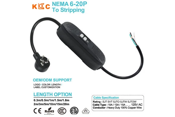
A white conductor visible in the product image should therefore not be classified as neutral from color alone. Color may result from cable availability, customer customization, or generic product artwork; the approved wiring drawing must determine function. Mistaking PE for a current-carrying conductor, or connecting a line conductor to the equipment grounding point, can lead to failed tests, an abnormal protective path, and assembly rework.
The Point-to-Point Drawing Must Cover Both Sides of the Module
This is not merely a plug-to-open-end cord. An inline module with TEST and RESET buttons sits between the two cable sections. The engineering drawing should not show only the NEMA blades and final leads; it should also define the module input, its approved monitoring or interruption paths, and the relationship between the output conductors and L1, L2, and PE.
The image cannot establish the module’s internal circuit, switched poles, or operating voltage. Buyers should require the exact model, circuit or wiring documentation, and applicable certification records. A module designed only for a 125V circuit, or one that interrupts only one conductor, cannot be assumed suitable for a 250V line-to-line system merely because it can be physically molded into a 6-20P cable. The production drawing must follow approved module data rather than a cable assembler’s assumption.
How Do Undefined Open-End Dimensions Increase Wiring Risk?
The equipment end may require an outer-jacket removal length, individual conductor breakout lengths, strip dimensions, and either bare leads, ferrules, ring terminals, or another treatment. If the order defines only overall length, field operators may need to cut the leads again, potentially removing identification labels, damaging strands, or leaving insufficient usable length.
The drawing should define overall length, plug-to-module length, module-to-open-end length, breakout length, strip length, and tolerances from consistent datums. Durable sleeves or labels can assist L1, L2, and PE identification, but they do not replace electrical testing. Where terminals are required, the terminal part number, material, plating, crimp height, and pull requirement should also be controlled to prevent a conductor-terminal mismatch and localized heating.
Why Is 12 AWG/3C Only a Baseline for a 20A Version?
If the complete assembly is intended for 20A service, 12 AWG/3C can serve as an engineering starting point. Conductor cross-section affects resistance, voltage drop, and temperature rise under continuous load, but the final selection also depends on length, jacket, ambient temperature, termination design, module rating, and finished-cord approval.
The SJT, SVT, SJTO, SJTW, and SJTOW options shown in the artwork should not be interpreted as proof that every jacket is approved for this 250V protected cord. Buyers should verify complete cable printing, conductor material, and actual AWG before production. If the inline module is limited to 15A, the complete assembly must follow the lowest-rated component; a 6-20P and 12 AWG cable do not by themselves justify a 20A finished-cord label.
Which Tests Can Find Wiring Errors Before Shipment?
The first is a point-to-point continuity test that verifies each NEMA blade, module path, and stripped lead. The second is a miswire and short-circuit check confirming that no unintended connection exists among L1, L2, and PE. The third is protective-earth continuity, verifying that PE remains correctly connected from the plug grounding pin to the equipment end. The fourth is TEST/RESET and fault-operation testing according to approved documentation.
Testing should also cover power-restoration behavior. For equipment capable of motion, heating, or automatic operation, manual and automatic reset modes create different restart behavior and must be defined in the specification and label. Trip threshold, trip time, monitored conductors, and switched poles should be tested against technical documents for the exact module rather than unverified generic values.
How Can OEM Production Build a Closed-Loop Wiring Control Process?
The purchase file should include the NEMA 6-20P 20A, 250V interface definition; protection-module manufacturer and part number; L1/L2/PE point-to-point table; wire gauge, conductor count and material, and jacket; segment and stripped-end dimensions; terminal specification; TEST/RESET and reset behavior; inspection requirements; labeling; and finished-assembly certification status.
First-article approval should compare the drawing, BOM, physical sample, cable printing, and test record together. The “125V AC, 10A/13A/15A” text in the promotional image conflicts with the standard NEMA 6-20P class and must be corrected in production documentation or supported with evidence for the exact module. Dongguan Kuncan Electronics Co.,Ltd recommends upgrading error prevention from color identification to a system of controlled drawings, isolated fixtures, point-to-point tests, and batch traceability, helping reduce L1/L2/PE miswiring, equipment rework, nuisance trips, and after-sales disputes.


USER EVALUATE
Here is the customer's evaluation of us