


How to Prevent 4-Wire Connection Errors: Checking L1, L2, N, and PE on a NEMA 14-30P Pigtail Cord
In OEM assembly for dryers, commercial laundry equipment, and other North American 30A equipment, an open-end power cord can eliminate on-site cutting, stripping, and some terminal-preparation work. The same convenience creates a risk: if the four conductors are not clearly defined, wiring rework, failed electrical tests, or an equipment-grounding path that does not match the design may result. When sourcing a NEMA 14-30P pigtail cord, Dongguan Kuncan Electronics Co., Ltd. recommends checking more than the plug shape and establishing a verifiable end-to-end definition for L1, L2, N, and PE.
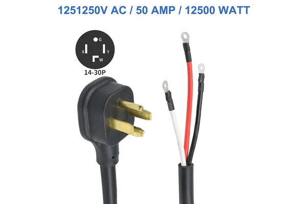
Confirm 14-30P, Not L14-30P or 10-30P
NEMA 14-30P is a straight-blade, four-prong male plug commonly rated 30A, 125/250V AC with a 3-pole, 4-wire grounding configuration. The four electrical paths generally correspond to L1, L2, N, and PE, with PE serving as the separate equipment-grounding conductor. This differs from the 3-wire non-grounding NEMA 10-30 and from the twist-lock NEMA L14-30P.
A purchase document stating only “30A dryer plug” or “4-wire power cord” may not exclude the wrong interface. Engineering drawings, product names, and packaging should consistently state “NEMA 14-30P, straight-blade, 30A, 125/250V AC, 3-pole 4-wire grounding” and include a front-view connector drawing and dimensional requirements. This reduces the risk of receiving a sample that cannot connect to the target receptacle.
Use Wire Colors as Identification Aids, Not as the Wiring Authority
Different conductor colors commonly help identify the four open-end leads, but color alone should not be the sole basis for production wiring. Images, supplier batches, customer harness specifications, and internal equipment rules may differ. If an operator assigns L1, L2, N, and PE from experience alone, an error may remain hidden until final testing.
A more dependable approach is to identify the correspondence between each plug contact and open-end lead on the approved engineering drawing, assigning each conductor as L1, L2, N, or PE. Production should include point-to-point continuity and wiring checks to verify that every lead reaches the specified blade. For OEM buyers, this converts a subjective color assumption into a drawing-controlled and test-verified process, reducing batch inconsistency.
Why Must L1, L2, N, and PE Remain Distinct?
L1 and L2 provide the line conductors and can form the higher-voltage circuit required by the equipment. N is the neutral conductor and may serve applicable loads within the equipment design. PE provides the equipment-protective grounding path. The actual load arrangement must follow the equipment circuit design and manufacturer-approved wiring diagram; it should not be inferred by the cord supplier or installer.
If N and PE are combined incorrectly, or PE is not connected to the equipment’s designated grounding point, the protective path may no longer match the intended design. If a line conductor reaches the wrong terminal, functional testing may fail or components may operate abnormally. The purchase drawing should identify terminal positions, symbols, and connection destinations, while qualified personnel should complete the equipment-side wiring.
How Can Pre-Crimped Terminals Save Time but Still Cause Rework?
The image shows prepared terminals on the four conductor ends. Pre-cutting, stripping, and crimping can reduce repetitive processing on an equipment assembly line, but only when the terminal width, thickness, stud-hole or insertion geometry, plating, insulation sleeve, crimp height, and strip length all match the equipment connection.
A terminal that does not match the conductor size, a loose crimp, damaged strands, or insufficient insertion depth can increase contact resistance and create localized temperature rise in a 30A application. The OEM specification should include a terminal drawing and tolerances, define pull-force and crimp-acceptance requirements, and require an actual terminal-block fit check, continuity test, and pull test during sample approval rather than accepting the terminal by appearance alone.
Why Is 10 AWG/4C Only an Engineering Baseline?
For a 30A NEMA 14-30P cord assembly, 10 AWG/4C can serve as a common engineering baseline. Conductor cross-sectional area, cable length, ambient temperature, equipment load, and routing method all affect voltage drop and temperature rise. The final conductor specification therefore needs confirmation against the complete product standard and project conditions.
The image cannot establish conductor material, actual AWG size, jacket designation, or temperature rating. Buyers should verify cable printing, material specifications, and test documentation. If SJT, STW, or SJTW construction is required, the target environment, ratings, and certification scope should be confirmed separately. A change in operating environment cannot be addressed by retaining the same plug while ignoring whether the cable construction remains suitable.
Build Four Layers of Error Prevention Before Production
The first layer is connector control: identify the straight-blade 14-30P configuration and verify it with a front-view drawing. The second is drawing control: fix the relationship between L1, L2, N, PE, the plug contacts, conductor colors, and terminals. The third is process control: define breakout length, strip dimensions, terminal orientation, crimp parameters, and pull requirements. The fourth is test control: conduct continuity, wiring, and project-required electrical tests on finished assemblies and retain batch traceability records.
Certification marks on individual components do not automatically establish that the complete assembly, after molding, cutting, and crimping, carries the same finished-product certification. Required labels, cable printing, test documents, and finished-cord certification status for the target market should be confirmed separately during quotation and sample approval.
The value of a NEMA 14-30P open-end power cord is not simply that it brings four conductors into the equipment. It comes from making the interface, conductors, terminals, and wiring definition repeatable and inspectable. Dongguan Kuncan Electronics Co., Ltd. recommends freezing the end-to-end wiring drawing before mass production and verifying the L1, L2, N, and PE relationships through continuity testing and an actual fit check. This helps reduce wiring errors, assembly rework, localized heating, and acceptance disputes.


USER EVALUATE
Here is the customer's evaluation of us